LED Troubleshooting - Using a Voltage Meter
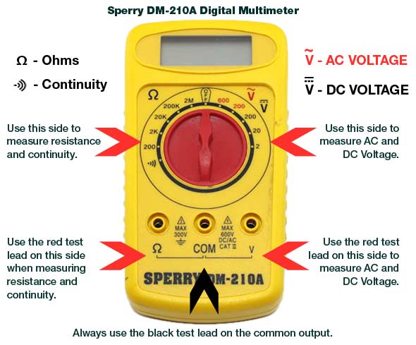
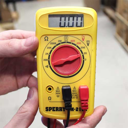
A Voltage Multimeter is the most important tool to have when troubleshooting an LED installation issue. They range in price from tens to hundreds of dollars. We use a basic Sperry DM-210A Digital Multimeter that can be found for $20 on Amazon. A voltage meter allows you to determine many issues that can effect an LED installation. The main tests that a voltage meter is handy for when troubleshooting is reading AC or DC voltage, checking continuity, and measuring voltage drop.
** Be certain to read all Multimeter instructions and warnings before use. To avoid electric shock use CAUTION when working with voltages above 40Vdc or 20Vac. Such voltages pose a shock hazard. Check the products minimum and maximum voltage requirements before use. To avoid possible electric shock, instrument damage and/or equipment damage, do not attempt to take any voltage measurements if the voltage is above the maximum listed or if the voltage is unknown**
Testing High Voltage AC Power
In order to test high voltage AC power you must first turn your multimeter to the proper setting on the range selector switch and put the test lead in the proper jack. On our multimeter the AC Voltage is marked in red. As you can see there is a 600 or 200 option. You want to choose an option higher than the voltage you are testing. In this case we are testing for 120VAC so we set the dial to 200. If you were testing for a voltage higher than 200VAC you would set the selector switch to 600.
Apply the test leads to the two points at which the voltage reading is to be taken, in this case one lead on your load and one lead on the neutral, polarity does not matter (NEVER TOUCH TWO POINTS WITH ONE LEAD, ELECRICAL SHOCK WILL OCCUR). Be careful not to touch any energized conductors with any parts of your body. Never ground yourself when taking electrical measurements. Do not touch exposed metal pipes, outlets, fixtures, etc., which might be at ground potential. Keep your body isolated from ground by using dry clothing, rubber shoes, rubber mats, or any approved insulating material. Never touch exposed wiring, connections or any live circuit conductors when attempting to take measurements. Always test your test equipment for proper operation before use.
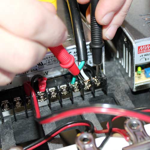
If everything was done properly you should get a voltage reading on the digital screen of your multimeter. In this case we were testing to be sure the power supply was receiving 120VAC input, and the reading came to 118.9VAC, which is acceptable. On any voltage reading a slight variation in either direction is to be expected.

Testing Low Voltage DC Power & Polarity
In order to test low voltage DC power you must first turn your multimeter to the proper setting on the range selector switch and put the test lead in the proper jack. On our multimeter the DC Voltage is marked in black. As you can see there is a 200, 20, or 2 option. You want to choose an option higher than the voltage you are testing. In this case we are testing for 12VDC so we set the dial to 20. If you were testing for a voltage higher than 20 you would set the selector switch to 200.
Apply the test leads to the two points at which the voltage reading is to be taken, in this case the red lead to your positive and the black lead to the negative, reverse polarity will give you a negative reading (NEVER TOUCH TWO POINTS WITH ONE LEAD). Be careful not to touch any energized conductors with any parts of your body. Never ground yourself when taking electrical measurements. Do not touch exposed metal pipes, outlets, fixtures, etc., which might be at ground potential. Keep your body isolated from ground by using dry clothing, rubber shoes, rubber mats, or any approved insulating material. Never touch exposed wiring, connections or any live circuit conductors when attempting to take measurements. Always test your test equipment for proper operation before use.
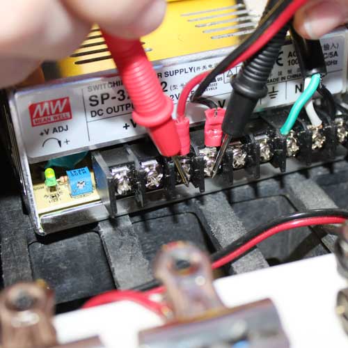
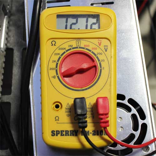
If everything was done properly you should get a voltage reading on the digital screen of your multimeter. In this case we were testing to be sure the power supply was outputting 12VDC, and the reading came to 12.12VDC, which is acceptable. On any voltage reading a slight variation in either direction is to be expected. If you reverse the polarity on your test leads the reading would have been -12.12VDC, this is a good way to test polarity if it is not marked on your LED product.
Testing for Continuity
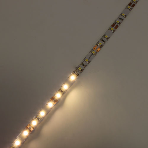
A continuity test is done to determine whether a circuit is open or closed. For example, a wall switch is closed when it is turned to the "on" position and it is open when it is turned off. An open circuit cannot conduct electricity. A closed circuit has continuity. This test should be done when current is NOT present. Always unplug the device or turn off the main circuit breaker before attempting a continuity test. Always test your test equipment for proper operation before use. If done properly a continuity test can be used to locate the exact place of an issue like a broken solder joint or lose wire, in this case the LED Strip Light has a broken solder joint.
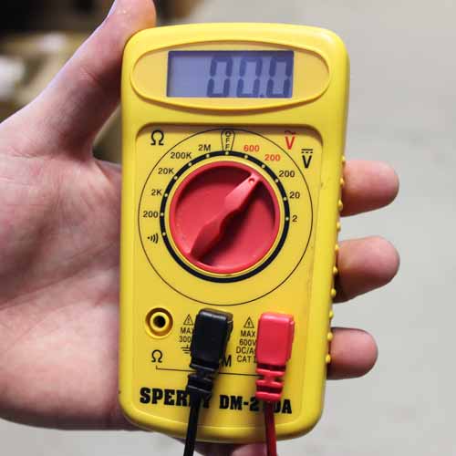
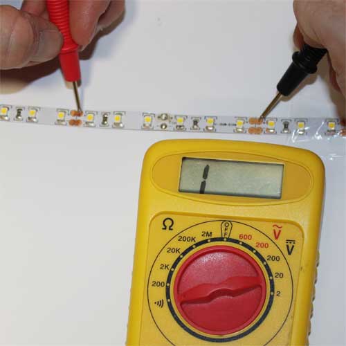
To test for continuity place your range selector switch to the lowest resistance setting or the emblem that looks like a sideways Wi-Fi symbol and put your red test lead to the appropriate jack. There are many options to test for resistance levels but these options are not very relevant to troubleshooting any common LED issue. You can test to see if your multimeter is working properly by touching your two test leads together, the unit should beep or register as a 0 reading, meaning no resistance is occurring.

Once you have found what you think is the source of your issue and you have your multimeter set to the correct setting, you can now begin to troubleshoot the source of the problem. In this case we tested the positive connection on each side of the LED Strip where we think the solder joint is broken. As you can see the voltage meter didn't go to zero and did not beep, meaning there is no continuity between those two points, meaning power can not continue between these two points. We can now check two points before and after the problem to be certain that this is the only place with an issue.
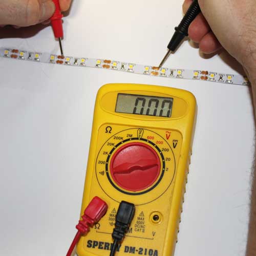
Once you have found what you think is the source of your issue and you have tested the continuity, you can now test continuity before and after the issue to be certain that this is the only problem source. By placing the two test leads on two positive copper pads before and after the broken solder joint the voltage meter tells me with a 0 display and beeping sound that there is continuity between these two points. I can now be certain that the broken solder joint is the source of the problem and with a quick overlap solder I can easily fix the problem.
Testing DC Voltage Drop
A common misconception when installing LEDs is that you can simply link together a large amount of LED product in a series without any issues. We do have some products that can be run further than others in a single series but in general the longer you run an LED product in a series the more voltage drop you will experience, especially when you are using long lengths of connection wire from your power source. A parallel connection is the best way to battle voltage drop in your LED product and knowing the voltage that your LED products are receiving is crucial to the lifespan and brightness of your LED products.
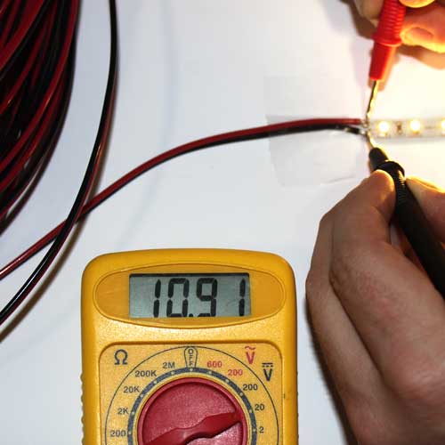
If you read the guide for testing DC Voltage above you should be familiar with the correct way to measure the output of a DC power Supply. In this case the power supply is outputting 12.12 Volts, as it's supposed to, but when I add 200ft of wire between the power supply and my lights, you will see the voltage drop that occurs. Keep in mind that the 200ft of wire is simply for demonstrational purposes. In any LED Lighting installation the shorter lengths of wire used the better and more even the light output will be.
After adding 200ft of 18AWG wire between my LED Lights and my DC Power Supply I can simply use the Multimeter test leads to measure the input voltage to my LED Lights. In this case the input is 10.91VDC at the beginning of the strip, so we lost over 1 volt throughout the wire. You should also test the end of your LED Installation as voltage drop continues to occur throughout LEDs. If the end of the LED run has voltage drop, supply power to both end and beginning to even out the voltage drop.
**Never adjust the trim pot on a power supply without the use of a voltage meter. This is not a proper way to make your lights brighter, over time improper voltage to your LED Lights will lessen the lifespan and could potentially be a fire hazard.**
You can adjust the voltage output on certain power supplies by a trim pot located on the front of the unit. Only our non-waterproof power supplies have a voltage adjustment trim pot. Simply turn the trim pot clockwise to increase and counter-clockwise to decrease and then re-test voltage at beginning of LEDs.

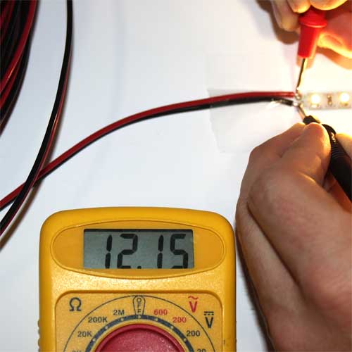
After adjusting the output voltage on your LED power supply you can now re-test the input voltage at the beginning of your LED Lights. After adjusting the trim pot my voltage to my LED Strip Light is now 12.15VDC, which is much more acceptable than 10.9VDC. Be certain to test voltage on all your LED Strip Lights, Optimal voltage is + or - 0.75V.